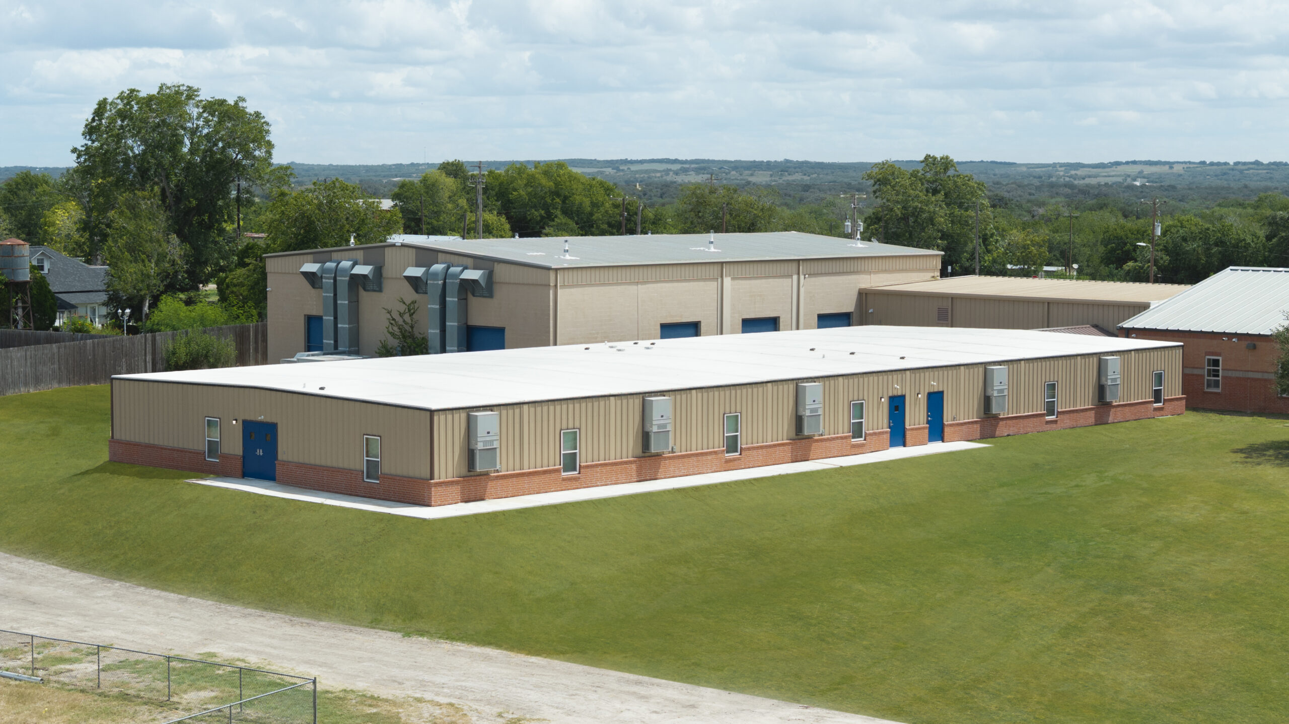
At 6:15 a.m., a project manager stands on a graded lot with a radio, a set of stamped drawings, and a delivery schedule that leaves little room for improvisation. The first transport rig is due shortly, but the building hasn't arrived as a finished project. It has arrived as a chain of dependencies: foundation elevations, crane access, utility stub-ups, rigging instructions, inspection requirements, and dozens of connection points that must agree within tight tolerances.
That distinction matters. Modular building installation isn't a delivery event. It's the project's most exposed quality-control window. Factory production can provide repeatable workmanship, but the field crew still has to place, align, connect, seal, inspect, and commission the modules under real site conditions. Research on prefabricated construction identifies on-site workmanship as the largest root cause of reported defects, accounting for 44.1% of identified causes in a systematic review (Sustainability systematic review). The practical lesson is simple: a calm set day comes from verified handoffs completed well before the crane arrives.
Table of Contents
- The Day the Modules Arrive
- Site Evaluation and Pre-Shipment Preparation
- Choosing and Setting the Foundation
- Utility Tie-Ins Before the Modules Land
- Craning, Lifting, and Setting the Modules
- Joining, Sealing, and Final Inspections
- Risks That Decide Every Install
The Day the Modules Arrive
At 7:20 a.m., the first trailer is already in the laydown area when the manifest raises a question. The paperwork lists module M-04, but the shipping tag reads M-05. The crane crew has not attached the slings, so the project manager stops the lift, checks the factory release package, and confirms the correct set sequence before either unit moves. That pause prevents a module from being placed on the wrong bearing points and then lifted again.
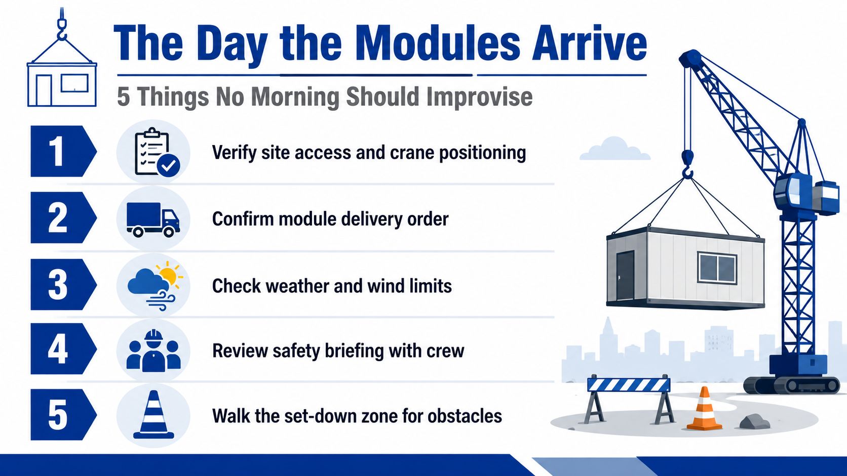
The arrival window should function as a controlled field inspection. Five handoffs require documented closure before the first lift:
- Shipping records: Signed manifests must match the BIM identifiers and the factory release package.
- Crane positioning: The crane pad needs documented bearing capacity and access clearance, and its location must match the lift plan.
- Foundation survey: Bearing points, anchor locations, and finished elevations must be staked and independently checked.
- Utility mapping: Electrical, plumbing, fire protection, HVAC, and data stub-ups must agree with the factory penetration drawings.
- Lift sequencing: The rigger, crane operator, project manager, and factory quality representative must review rigging points, the sequence, and the contingency plan.
A transport manifest mismatch is only one field failure. Before the module leaves the trailer, compare its ID with the delivery list, inspect the wrap, corners, windows, trim, and exposed finishes, and verify that transport blocking remains secured beneath the floor cassette. Record weather conditions against the lift chart. Check the set-down zone for loose materials, standing water, temporary fencing, and unmarked obstructions.
The handoff is where installation begins
The factory inspection record describes the unit that left the plant. Receiving inspection verifies the unit that reached the site, including transport damage, position-specific identification, lifting hardware, and protective restraints. Factory QA can be consistent while field conditions still introduce damage, tolerance problems, or interface conflicts.
Practical rule: If a defect is visible before the lift, photograph it, identify it on the receiving report, and assign ownership before the module leaves the trailer.
Treat delivery as the first opportunity to verify alignment, condition, and responsibility. Decisions made during that handoff determine whether the crew proceeds with confidence or creates concealed rework that appears only after joining and finishing.
Site Evaluation and Pre-Shipment Preparation
Site readiness starts with information, not excavation. The geotechnical report should verify soil bearing conditions against the structural drawings, while the civil and structural teams establish finished floor elevation from floodplain information, drainage requirements, and applicable code criteria. A topographic survey should identify soft areas, uncontrolled fill, drainage conflicts, and grading zones that may require over-excavation or stabilization.
The access corridor deserves equal attention. The longest module may control the entire route, including turning movements, bridge restrictions, overhead utilities, gate widths, and temporary removal of signs or street furniture. The team should walk the route with the transport provider rather than relying only on aerial imagery or a plan set. The laydown zone also needs measured dimensions, stable ground, lighting, and a clear path between the trailer and the crane.
Five documents that should be in the release file
Before the factory authorizes shipment, the owner should hold:
- Geotechnical report, reviewed against the foundation design and bearing assumptions.
- Stamped site survey, showing benchmarks, finished elevations, setbacks, and bearing locations.
- Haul-route assessment, including clearance checks and transportation restrictions.
- Laydown and crane-pad plan, with dimensions, surface preparation, and exclusion zones.
- Pre-shipment factory inspection record, including module IDs, open items, protective measures, and release approval.
Modular foundations tolerate less grading uncertainty than many conventional site teams expect. A module base is designed to bear on defined points or a defined plane. If the supporting surface is uneven, the installer may compensate with shims or adjustments, but excessive correction can transfer loads into frames, floors, finishes, and connection points in ways the factory never intended.
Permitting coordination belongs in this readiness review too. A useful reference for owners working through approvals is this step-by-step guide to the modular construction permitting process, particularly where local plan review, inspections, and modular building requirements overlap.
| Check Item | Acceptance Criteria | Owner of Sign-Off |
|---|---|---|
| Soil and grading | Conditions match the structural and civil design assumptions | Geotechnical engineer and civil engineer |
| Survey control | Benchmarks and bearing elevations are documented and protected | Surveyor and structural engineer |
| Haul route | Route is passable for the approved transport configuration | Transport provider and site manager |
| Crane pad | Surface and bearing conditions support the planned operation | Crane contractor and engineer |
| Utilities | Stub-up locations match the approved coordination drawings | MEP contractors and project manager |
| Factory release | Module identity, condition, and open items are recorded | Factory QC representative |
Choosing and Setting the Foundation
Foundation selection affects more than support. It determines where the module bears, how the crane approaches, how installers access the underside, and whether the building can later be moved. It also fixes practical limits on module dimensions and connection geometry, so changing the foundation concept late can force redesign rather than a simple site adjustment.
| Foundation Type | Typical Cost per Sq Ft | Install Time | Best Soil Condition | Relocation Friendly |
|---|---|---|---|---|
| Concrete pier blocks on compacted gravel | Project-specific | Generally quick | Competent, well-drained soil | Often suitable |
| Monolithic slab-on-grade | Project-specific | Moderate, with curing and inspection requirements | Uniform bearing soil | Usually limited |
| Perimeter footing with interior piers | Project-specific | Moderate | Sites needing defined perimeter and interior support | Limited |
| Helical or driven piles | Project-specific | Often useful where excavation is difficult | Poor, variable, or frost-sensitive soil | Depends on design |
Cost per square foot shouldn't be filled in with a generic allowance. Site conditions, engineering, local labor, frost depth, access, and code requirements can change the comparison substantially. For commercial work, a contractor resource such as Atlanta Concrete Solutions commercial foundation services can help owners frame the concrete scope, but the structural engineer still controls the foundation design and acceptance criteria.
Set the bearing points, not just the outline
The installation sequence begins with survey control. A total station establishes the building lines and bearing coordinates. Pier caps, slab edges, or piles are installed to surveyed elevations, and anchor bolts are placed from the factory base drawings rather than from an approximate architectural footprint.
Before shipment, the surveyor should verify every bearing point, anchor location, and critical elevation. The result belongs in the release package. If the foundation is adjusted after that survey, the affected locations need to be rechecked before the transport schedule is treated as firm.
A small error at the base can become a much larger problem at the marriage wall, roof seam, window line, or corridor threshold. Installers can correct minor discrepancies through approved shimming and adjustment. They shouldn't be asked to force a misbuilt foundation into alignment with a finished module.
Utility Tie-Ins Before the Modules Land
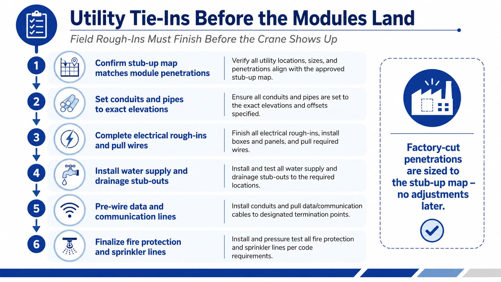
Factory-cut penetrations are built around a specific stub-up map. The field trades must therefore complete and verify the rough-ins before the crane arrives, not after the modules are sitting over them. A pipe or conduit that enters from the wrong side can turn a planned connection into demolition inside a finished wall.
The project manager should conduct one coordination walk with the electrical, plumbing, HVAC, fire-suppression, and low-voltage contractors. Each trade needs to confirm the location, elevation, sleeve size, service direction, and protection of every penetration. The electrical contractor should verify the panel base, main bonding, grounding electrode, and service path. The plumbing contractor should pressure-test and prepare the water service, then confirm that sanitary or septic connections align with the factory manifold layout.
The data contractor needs more than an empty conduit. Backbone cabling should reach the telecom backboard or designated communications location, with identification, protection, and enough slack for the final termination. The fire-protection contractor should confirm sprinkler and alarm interfaces before the modules obscure access.
Photograph the interface before covering it
Every stub-up should be photographed with a tape measure visible in the frame. The photo should show a fixed reference, the measured offset, the elevation, and the trade responsible for the installation. Those records give the set crew a usable field reference and provide evidence if a connection is later found out of position.
- Electrical: Confirm conduit path, service equipment location, grounding, and panel access.
- Plumbing: Verify pressure testing, drainage slope, sleeve protection, and connection offsets.
- HVAC: Match supply, return, condensate, and equipment interfaces to the module drawings.
- Fire protection: Confirm sprinkler mains, risers, alarm devices, and firestopping requirements.
- Low voltage: Pull backbone cabling to the communications point, then label both ends.
A contractor experienced in construction plumbing for remodels can be a useful resource for coordinating complex field plumbing work, but modular installation requires the additional discipline of matching every connection to the manufacturer's interface drawings.
Electrical standards and local requirements should be reviewed before field rough-in is closed. The electrical standards and requirements guide for mobile office trailers offers a relevant reference point for planning service and safety checks.
Craning, Lifting, and Setting the Modules
At sunrise, the crew gathers for a tailboard meeting. The rigger has the lift drawings, the crane operator has the load chart, the project manager has the sequence, and the factory representative has the module-specific handling instructions. The group reviews sling locations, spreader bars, tag lines, radio channels, exclusion zones, and the signal person who controls each movement.
The crane must be selected for the actual lift, not the module's empty shipping weight. Rigging, spreader bars, radius, boom configuration, ground conditions, and wind exposure all affect capacity. A capacity chart reading near the required radius should leave a practical operating margin. The crane's maximum advertised reach has no value if the load chart doesn't support the lift at the planned position.
| Module Weight (tons) | Max Radius (ft) | Minimum Crane Capacity (tons) | Typical Boom Length (ft) |
|---|---|---|---|
| Project-specific | Project-specific | Determined from the engineered lift plan | Determined from site geometry |
| Project-specific | Project-specific | Confirmed with rigging and radius included | Confirmed by crane contractor |
| Project-specific | Project-specific | Verified for the heaviest planned pick | Verified against obstructions |
The table is intentionally project-specific. A responsible lift plan uses the manufacturer's module weight, the rigging weight, the exact pick radius, and the selected crane configuration. It doesn't substitute a generic crane size for an engineered review.
The set sequence rewards patience
Before each module leaves the trailer, the crew confirms its ID and destination. The spotter checks the travel path, the rigger confirms the sling points, and the operator takes tension gradually so the team can see whether the module lifts evenly. A sudden tilt, shifting restraint, or unexpected contact is a stop signal.
The survey team should verify pier or bearing elevations before placement, using a transit or laser level. Correcting a heavy module after it has landed is slower and riskier than identifying the discrepancy first. Once the module is hovering above its position, the spotter guides it into alignment with clear radio calls, while the installers prepare approved shims, anchors, and connection hardware.
Set-day rule: The crane should wait for a decision. The crew shouldn't hurry a module into a foundation that hasn't been verified.
Wind limits depend on the module's sail area, rigging configuration, crane manufacturer's requirements, and the engineered lift plan. The project safety plan must define the hold threshold before work begins, with a designated person monitoring conditions and authority to stop the operation.
Teams needing a basic operational reference can review this mobile crane operation guide, while the project-specific lift plan remains the controlling document. Telescopic equipment may also form part of the access strategy, as described in this guide to a telescopic boom lift, but it doesn't replace the crane required for module placement.
Joining, Sealing, and Final Inspections
After the last module is seated, the installation becomes a quality-control window. Separate boxes must perform as one building, with aligned floors, walls, roofs, utilities, fire assemblies, and egress routes. The team should treat every connection as a potential source of rework until it has been measured, tightened, sealed, and documented.
Start with the marriage walls and inter-module connections. Compare their locations with the approved drawings, check that bearing and joint conditions match the design, then torque structural hardware to the manufacturer's requirements and record each result. Verify that tightening has not distorted finished surfaces. Floor, ceiling, and roof seams receive the specified gaskets, fire-rated sealants, cover plates, flashing, and weatherproofing for the jurisdiction and assembly type.
The roof marriage joint deserves close inspection. Water can enter through a narrow discontinuity and stay hidden until insulation, finishes, or framing show damage. A weather-tight seal depends on clean substrates, compatible materials, continuous application, proper tooling, and inspection before concealment.
Defects concentrate at the field interface
Field assembly introduces variables that factory QA cannot observe, including transport settling, shimming, connection torque, and the final alignment of adjacent modules. Verify those conditions on site rather than treating factory records as proof of the completed building.
A recent BIM-focused study reported recurring installation-accuracy and on-site cutting problems in prefabricated component work. Related research validated laser-scanned point clouds and automated geometric assessment against manual measurements (BIM and installation-quality research). The project team can compare approved BIM dimensions with total-station readings, laser levels, or point-cloud scans, then resolve deviations before finishes conceal them.
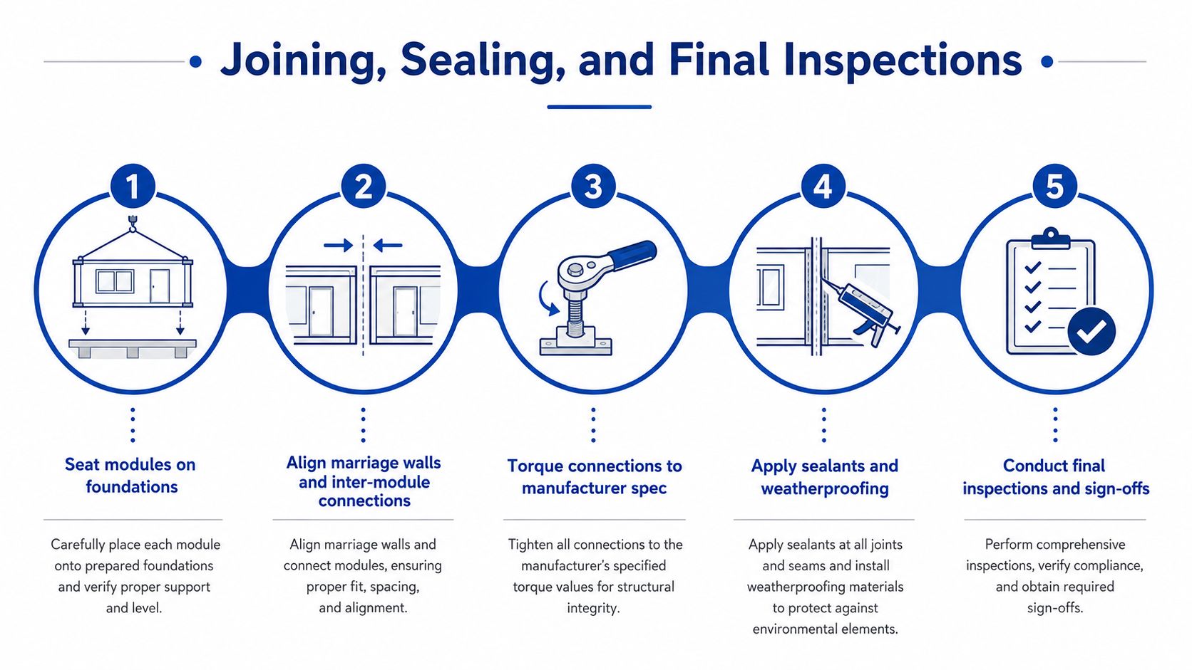
The inspection sequence should cover structural connections, firestopping, mechanical and electrical cross-module connections, plumbing tests, alarm addressing, accessibility clearances, doors, thresholds, and emergency egress. Inspectors often concentrate on the points where factory-built assemblies become one permitted building. Invite the relevant inspectors early enough to close documentation gaps without leaving the finished building idle.
A visual overview of the field sequence can supplement the written inspection plan:
Risks That Decide Every Install
The crane is visible, but it is rarely the first source of trouble. Procurement gaps, code interpretation, incomplete drawings, and inexperienced crews can send a project into rework before lifting begins. Treat installation as a quality-control window. Verify each interface while it is still accessible, rather than assuming factory inspection guarantees field conditions.
The U.S. permanent modular construction market reached $20.5 billion in 2025, with about 5.1% of construction activity in key market segments, and the Modular Building Institute projects 6.5% compound annual growth through 2030 (Modular Building Institute industry analysis). Growth supports more standardized practices, but every project still depends on accurate site information and coordinated decisions. Another industry analysis describes a fragmented market with more than 700 modular construction companies, including more than 100 firms operating for at least 50 years, while more than 500 players generate less than €50 million in revenue (industry analysis summarized by Fortune Business Insights). Evaluate a supplier's installation controls, not factory capacity alone.
A day-zero checklist
Assign an owner, verification date, and escalation route to each item:
- Stamped drawings: Confirm approved structural, architectural, MEP, and fire documents are available on site.
- Foundation survey: Recheck bearing points near the set date and record movement or site changes.
- Stub-up records: Send measured utility photographs to affected trades and the factory representative.
- Rigger credentials: Verify qualifications, lift-plan participation, and radio procedures.
- Weather holds: Put wind, lightning, visibility, and ground-condition limits in writing.
- Contact tree: List the factory production manager, transport lead, rigger, crane operator, site superintendent, and permitting contact.
Permitting and financing can delay a completed shipment. The Modular Building Institute identifies financing gaps, inconsistent permitting and regulation, uneven project pipelines, design coordination problems, and limited modular experience as adoption barriers (2026 market update). Resolve those issues before fabrication is authorized or delivery is scheduled.
Pacific Mobile Structures, Inc. provides turnkey modular construction services, coordinating foundations, off-site assembly, transportation, utility connections, and on-site installation. Visit Pacific Mobile Structures, Inc. to discuss a project-specific plan covering interfaces, logistics, and inspections before delivery.